Standard Slot Size
Holes or slots in the arrow side member of a joint for plug or slot welding must be indicated by placing the weld symbol on the side of the reference line toward the reader (A, fig. 3-11).
- Standard Mail Slot Size
- Standard Slot Size
- Standard Slot Sizes Sheet Metal
- Mail Slot Size
- Standard Slot Sizes Metric

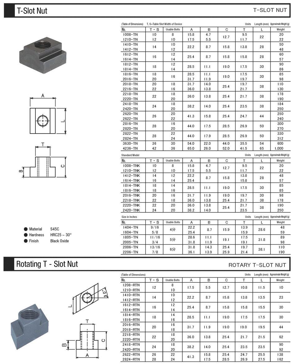
Flathead screwdrivers range in size from mere millimeters up to bigger fractions of an inch. Two measurements are noted for each screwdriver: the length of the shaft and the width of the head. Examples of flat head screwdriver sizes in inches include 3/32 by 1 1/2, 3/16 by 1 1/2, 1/8 by 4, 3/16 by 4, and 1/4 by 4. Engineering Hardware Standards Dimension Table for T-Slots, Bolts, and Nuts per. American National Standard T-Slots ANSI/ASME B5.1M-1985. Width of tongue used with the T-Slots will be found in the complete standard, B5.1M.
Holes or slots in the other side member of a joint shall be indicated by placing the weld symbol on the side of the reference line away from the reader (B, fig. 3-11).
Neither the plug weld symbol nor the slot weld symbol may be used to designate fillet welds in holes.
Plug or Slot Weld Diagram

Arrow Side & Other Side Indication of a Slot or Plug Weld Symbol

Slot or Plug Welding Symbol
Plug & Slot Welds Indicated by Arrow on Side of Joint
Plug Weld Dimensions
Dimensions of plug welds must be shown on the same side of the reference line as the weld symbol. The size of a weld must be shown to the left of the weld symbol.
The included angle of countersink of plug welds must be the user’s standard unless otherwise indicated.
The included angle of countersink, when not the user’s standard, must be shown either above or below the weld symbol (A and C, fig. 3-34).
The pitch (center-to-center spacing) of plug welds shall be shown to the right of the weld symbol.

Dimensions, Details and Surface Contour of Plug or Slot Welds
Standard Mail Slot Size
Depth of Filling of Plug and Slot Welds
Depth of filling of plug and slot welds shall be completed unless otherwise indicated. When the depth of filling is less than complete, the depth of filling shall be shown in inches inside the weld symbol (B, fig. 3-34).
Surface Contour of Plug Welds and Slot Welds
Plug welds that are to be welded approximately flush without recourse to any method of finishing must be shown by adding the finish contour symbol to the weld symbol (fig. 3-35).
Standard Slot Size
Plug welds that are to be welded flush by mechanical means must be shown by adding both the flush contour symbol and the user’s standard finish symbol to the weld symbol (fig. 3-36).
Slot Weld Dimensions
Dimensions of slot welds must be shown on the same side of the reference line as the weld symbol (fig. 3-37).
Standard Slot Sizes Sheet Metal
Details of Slot Welds

Mail Slot Size
Length, width, spacing, included angle of countersink, orientation, and location of slot welds cannot be shown on the welding symbols.
Standard Slot Sizes Metric
This data must be shown on the drawing or by a detail with a reference to it on the welding symbol, in accordance with location specifications given in paragraph 3-7 (D, fig. 3-33).